


Balance of Propulsive Forces
Balance of Propulsive Forces
In this newsletter I continue analysis of forces
in rowing, and focus here on the balance of propulsive forces. The force Fbx
acting on the boat was previously defined (RBN 2019/01) as the difference
between the pin Fpx and stretcher forces Fsx:
Fbx = Fpx – Fsx (1)
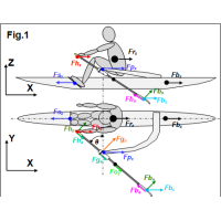
The propulsive force applied
to the rower’s centre of mass CM Frx was defined as the
sum of reaction forces at the stretcher Fsx and the handle Fhx
(Fig.1), where the latter Fhx is the sum of X
components of normal Fhn and axial Fha
forces at the handle. The latter Fha was assumed to be
equal to the measured axial gate force Fga, but in fact they could
be slightly different because of the axial blade force Fba and
centripetal force of oar rotation Foc acting only on the
gate axial force Fga.
Frx = Fsx - Fhx
= Fsx – (Fhn cos(θ) + Fga sin(θ)) (2)
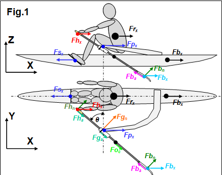
where θ is the oar angle. Fig.2 shows
these forces in M1x at 35.5spm, the same sample as in RBN 2019/01.
The propulsive force applied to the rower-boat
system Fpsysx was defined as the sum of the forces on the
boat Fbx
and rower’s CM Frx (Eq.1,2). The stretcher force Fsx
is cancelled, so Fpsysx is the difference between X forces at
the pin Fpx and handle Fhx:
Fpsysx = Frx + Fbx = (Fpx –
Fsx)+ (Fsx - Fhx) = Fpx - Fhx (3)
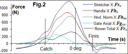
During the middle of the recovery, Fpsysx
is close to zero as expected (Fig.3,1), but the system propulsive force becomes positive even before the catch
(2), which could be an effect of the oar centripetal Foc and rotational
inertia force Fo.in (RBN 2015/05). During the recovery, the oar CM
(located on the outboard) moves forward, so it’s kinetic energy is transferred
to the system at oar deceleration before the catch (2). After the finish, the
oar inertia force is negative, which decreases the system propulsive force (3).
The X component of the oar
inertial force was defined with the angular oar acceleration α derived
from the oar angle, the oar moment of inertia Io at the pin (1.6 kgm2)
and distance between CM and the rotation axis LoCM (0.42m
from pin):
Fo.in = Io α / LoCM cos(θ) (5)
Oar inertia force explains the
increasing of the total propulsive force before the catch (Fig.3,2) and its
drop after the finish (3).
The total propulsive force
measured from the pin/gate and handle Fpsysx was compared with
one used traditionally as the forward component of the blade force Fbx
defined through the handle force Fh, gearing ratio (inboard Lin
to outboard Lout) and oar angle θ:
Fbx = Fh (Lin/Lout)
cos(θ) (6)
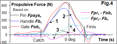
These two forces were quite similar during the
first half of the drive (Fig.4,1), but then, Fpsysx
appeared to be much higher than Fbx (2). To eliminate sensor
error, the propulsive force at the blade Fobx was derived from the
oar sensors, which were completely independent from the pin sensor:
Fobx = (Fgn – Fhn)
cos(θ) (6)
where Fgn is the normal gate
force and Fhn is normal handle force. Two forces Fpsysx
and Fobx
matched quite well together - a small difference between them (3) could be
related to the axial force at the blade Fbax and oar centripetal
force Foc, which were not measured from the oar sensors in
Fobx,
but affected the total propulsive force Fpsysx.
The significant difference in
Fpsysx-Fbx
during the second half of the drive (4) could be explained by a shift of the
centre of pressure at the blade inwards, which decreases actual outboard and
increases the blade force, so Fbx defined through the
handle force and gearing appeared to be underestimated. This was my previous
idea, when I analysed changing the ratio of handle/gate forces (RBN 2014/02).
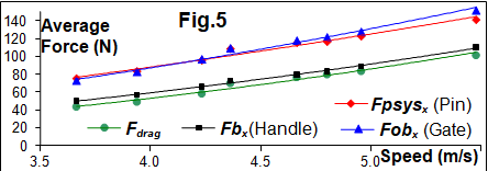
The best match was found between the drag force
and Fbx - the blade
propulsive force obtained with the traditional method of using the handle force
only (r=0.991). On average, the blade propulsive
force was 8.3% higher than the boat drag force, which can be easily explained
by additional air drag resistance. Two other versions of the propulsive
force also had very high correlation with the drag force (r=0.998), but Fpsysx (obtained from pin-handle) was 53.2% higher,
and Fobx
(from gate-handle) was 57.1% higher than the drag force. This placed doubts
on my previous hypothesis about there being shorter actual outboard and higher
blade force during the second half of the drive.
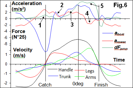
A possible solution to this puzzle, the mysterious
extra force at the pin-gate, is to relate it to some inertial force in the
rower-boat system. To do this, the found above difference
in propulsive forces dFprop = Fpsysx- Fbx was compared with accelerations of the
boat aboat
and rower’s CM arower (Fig.6), where aboat was measured directly and arower was derived from measured seat and rower’s trunk movements added to the boat
acceleration. Velocities of the handle and rower’s body segments are given as a reference of the phases
of the stroke cycle.
Here, I should refer to my
model of power conversion into kinetic energy (RBN 2018/11), where point 9 can
be appended as follows: “Two components of the system, the rower and the boat,
not only receive kinetic energy through the oar, but also exchange it between
themselves. … Energy exchange also happens during the drive: after the catch,
the rower actively accelerates his CM using the leg drive, taking kinetic
energy from the boat, which receives negative acceleration”. At the catch, this
exchange happens through the stretcher force, which is not accounted in
propulsion equation No. 3, so it is not reflected in the difference of
propulsive forces dFprop. A small value of this difference
at the catch (Fig.6,1) could be related to oar linear inertia force, which
pushes the pin and looks like propulsive force.
Currently, all this is a
hypothesis and there is still a lot of work required to understand the
mechanics better and to develop methods of analysis for propulsive and internal
forces in the rower-boat-oar system. Say, in the example above, the rower pulls
the fixed oar producing the handle force, which subtracted from the gate force
in eq.3, so “propulsive” force should be zero. Perhaps, some other factors are
at play here: Gearing? Seat friction? Axial oar forces?
In conclusion, the mechanics in the rower-boat-oar system are quite a complex issue, where
the main challenge is separation of propulsive and internal forces mixed in the
measurements at the handle, gate-pin and stretcher. Currently, a complete explanation for the phenomenon of higher gate-pin
force during the second half of the drive is still not completely clear to us.
All suggestions and hypotheses are very welcome.
Acknowledgements: Thank you to WinTech
Racing Boats and Oarsport Ltd. for their support of this study.
©2019 Dr. Valery Kleshnev www.biorow.com