


History of rowing force measurements
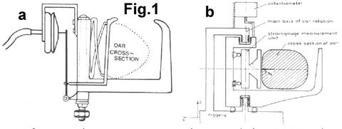
The age of force measurements in rowing surpasses the age of the modern Olympic Games: the first study of a military doctor Leon Passover from Saint-Petersburg, Russia was published in 1893 (1). In that study, the rower’s force applied to the handle was determined using oar shaft deformation, registered with a mechanical system of levers mounted onto the oar (from 10). In 1896, Oxford faculty member E.C. Atkinson did work on the “Rowing Indicator” (2), followed by a French study of Le Fevre in 1904 (3). Schematics of the device in the second study (Fig.1,a) could be found in a comprehensive review of Dal-Monte (9): the gate force was measured by means of a spring in the oarlock, connected through a hydraulic system to an arm of an oscilloscope. A similar design based on strain-gauges (Fig.1,b) was used by Volker Nolte in 1980 (7). Both instrumented oarlocks measured only positive propulsive force, so measurements of negative force - which may be useful for detecting technical faults and for biomechanical modelling of a balance of forces in the whole rower-boat system, was not measured.
After strain-gauges were invented in 1938, they were widely used for force measurements in rowing (4, 5, 6). Strain-gauges were usually glued directly to the oar shaft, which works as a load cell, so the oar shaft deflection was measured – this is directly proportional to the handle force applied by the rower. However, it was not possible to reuse the sensor on another oar, which made this method quite material and time consuming.
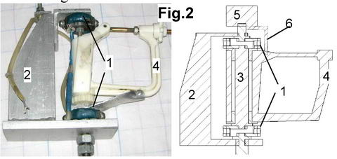
Our history of developments in rowing biomechanics began in 1987, when the first prototype of instrumented oarlock was made. It was based on two ring-shaped load cells with strain-gauges (Fig.2, 1), which rotated with bush-bearings on a special bracket (2) and were connected to the original pin (3) with a plastic swivel (4) mounted on it. Similarly to Nolte’s design, the oar angles were measured with a potentiometer (5) mounted on top of the bracket and connected to the swivel with a small arm (6). The oarlock measured all forces applied by the oar (both positive and negative) and allowed pitch adjustment in the same way as in the original unit. A disadvantage of this system is the necessity to remove the original pin and a heavy and bulky bracket.
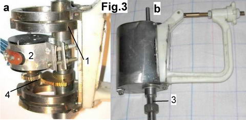
The next design came very soon after in 1988 and was patented (8). A structure with four ring-shaped load cells (Fig.3,1) incorporated a potentiometer (2) for angle measurements, connected to a stationary pin (3) through a cog-wheel gear (4). Advantages of this design were the possibility to keep the original pin and quite a compact size. Disadvantages: it was quite heavy, complicated to manufacture, expensive, and had no pitch adjustment.
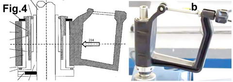
It is interesting that our 1988 design was referenced in Paul Haines’s patent (11) for an instrumented oarlock, which design was completely different from our prototype. This oarlock (Fig.4) is used in Peach Innovations measurement system, and this is the only known device, which measured force fixed in the boat reference frame. This fore-aft force was called “a propulsive force”, and was discussed earlier, see RBN 2010/03.
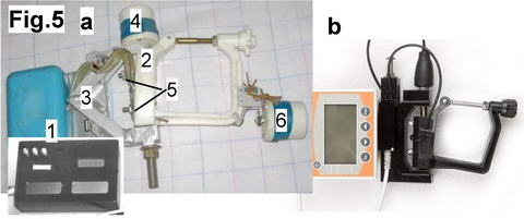
Our third design came in 1992 (Fig.5,a) and was incorporated with an electronic module (1), which calculated rowing power from measured force and angle, and displayed these numbers in a boat in real time. A special shaft inside the swivel (2) served as a load cell with strain-gauges. The shaft rotates about two ball-bearings mounted on a bracket (3), and its top end is connected to a potentiometer (4) for angle measurements. The swivel was connected to the shaft with two screws (5), which provided pitch adjustment. Additionally, this oarlock was able to measure vertical oar angles with the second potentiometer (6) mounted on the swivel and connected to the oar with an arm. In 2001, this design was licensed to Austrian WEBA-Sport company and used in their Row-X system (Fig.5,b).
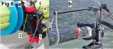
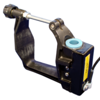
The third design worked quite well, but the only disadvantage was the necessity to replace the original pin, so it was not possible to use it with new types of riggers where the pin is mounted from both sides in a C-bracket. To overcome this problem, the fourth design was made in 2005, where the original pin could be used on any rigger type. This model was based on a U-shaped load cell (Fig.6a, 1) with binocular-shaped holes in it (2) where strain-gauges were glued. The cell rotated on the pin through bushings at the ends (3), and was connected to a swivel with two screws through shims (4) for pitch adjustment. This load cell was able to measure both normal and axial forces using holes with strain-gauges in its vertical and horizontal (5) parts. The angles at the oar were measured with the standard 2D sensor mounted on top of the pin and connected to the oar shaft with an arm and bracket Fig.6, b), so it is a separate device from the oarlock which could be considered as a disadvantage.
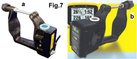
The fifth generation of our instrumented oarlocks was developed in 2011 (Fig.7,a). Its compact structure comprises of a cylindrical load cell for 2D force measurements (both normal and axial forces could be measured) and a magnetometer for angle measurements (a magnet is fixed on the pin at the bottom of the oarlock). The oarlock rotates on a plastic bushing on the original pin, so it can be used with all rigger types. Originally, a wired version was used with the BioRowTel telemetry system, and in 2013 this design was licensed to Nielsen-Kellerman and was used as a base in development of the EmPower wireless oarlock (Fig.7,b).
Devices for measurements of other rowing forces (at the handle, stretcher, and seat) were developed by us in parallel with the instrumented oarlocks, and will be described in future publications.
References
1. 1893. Passover L.P. How rowing affects lower extremities and the rower's performance. Thesis at Sankt-Peterburg Medical Academy (from Zatsiorsky, 10).
2. 1896. Atkinson E. A rowing indicator. Natural Science. 8. 178. (from Dal Monte, 9).
3. 1904. Le Feuvre and Pailliote. Elude graphique du coup d'aviron en canoe Bull. de l'Association Techn. Maritime. Paris. 115. (from DalMonte, 9).
4. 1966. Shvedov A.M., Shebuev A.N. Rowing technique. In Grebnoi sport [Rowing sport] (pp. 18-38). Moscow: FiS.
5. 1968. Ishiko, T. Application of telemetry to sports activities. In J. Wartenweiler, E. Jokl, & M. Hebbelinck (Eds.), Biomechanics I (pp. 138-146). Basel/New York: Karger.
6. 1968. Lazareva A.M., Zhigalov J.A., Morzhevikov N.V. Strength aspect in oarsmen's performance. Theory & Practice of Physical Culture, 9, 15-18.
7. 1985. Nolte V. Die Effektivitat des Ruderschlages. Banels & Wernitz.
8. 1988. Kleshnev V.. Device for power measurement in rowing. Patent of USSR N 1650171.
9. 1989. Dal Monte A., Komor A. Rowing and sculling mechanics. In C.L.Vaughan (Ed.), Biomechanics of sport (pp. 53-119). Boca Raton, FL: CRC Press
10. 1991. Zatsiorsky V.M., Yakunin N. Mechanics and biomechanics of rowing: A review. International Journal of Sport Biomechanics, 7, 229-281.
11. 2006. Haines P. Force Sensing System. US Patent 7 114 398
©2018 Dr. Valery Kleshnev www.biorow.com